Some research & development projects
Project 1: Flexible Vehicle Simulation and Control System Design
1. Rigid Model of Vehicle Dynamics
Vehicle rigid model is based on the classical laws of theoretical mechanics. The model has been composed in the body-fixed reference frame and contains all necessary transformations of motion parameters to Earth-fixed frame and flight-path frame. The smooth and step changes of mass and moment of inertia, center of mass drift in relation to the points of control forces application are taken into account in the model. Smooth variations of inertial parameters are determined by fuel and oxidant consumption, and step changes are determined by detaching the separate parts of vehicle. The effects of rotary accelerations of engines at vehicle control and Coriolis forces at the complex movement of masses are also taken into consideration. Input parameters for simulation are: control forces and moments of forces, integral air forces and moments of forces which depend on vehicle attitude, altitude and flying speed. Acceleration of gravity dependence on altitude is taken into account. Output controlled parameters are: the vehicle attitude angles and their derivatives (the 1-st and 2-d ones), coordinates, velocities and accelerations in the arbitrary frame of reference, and also angles of attack and slip. All output parameters can be shown as arrays of numbers, charts or 3-D animations. Outcomes of each experiment can be saved for using by other program modules. If necessary, the model of rigid vehicle can be supplemented by models Flexible Model of Vehicle Dynamic, Vehicle Parameters Identification, Local Aerodynamic Loads, Sloshing in Tanks, Different Engines Models, and also modules for the analysis and reduction of control system Control System Analysis, Synthesis and Optimization and Order Reduction and Robustness Providing.
2. Flexible Model of Vehicle Dynamics
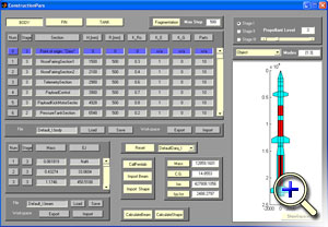
Flexible model of vehicle is the most complex program module. For the description of vehicle elastic vibrations the physical analog as the beam with varying cross sectional properties has been used. Elastic vibrations of this beam are summarized with output of Rigid model of vehicle dynamics. The program is equipped with a graphic interface, which allows inputting and editing in a wide range the parameters of any symmetrical constructions as it is shown in a figure.
 view movie
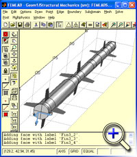
The interface allows changing dimensions and mass-elastic properties for each section of vehicle employing data tables. All changes are given in the graphical representation. The hollows (tanks) for filling with consumed material (fuel, oxidant) are chosen with the help of graphical interface. Peculiarities of these tanks discharging during the flight depend on engine type Different Engines Models. For simulation of vehicle elastic properties the method of separation of the continuous beam on discrete fragments joint by weightless elastic connections is used. For this reason all stages of vehicle are divided into fragments. All fragments have the form of a truncated cone. For all fragments the geometrical sizes, material (density) and rigidity are assigned. Input data is transformed by the program into matrix of mass and rigidity for the simplified model of a beam with free ends. This information is used for calculation the natural frequencies, the shapes of bending oscillations, the 1-st and 2-nd derivatives of shapes by solving the eigenvalues problem. The number of modes and accuracy of natural frequencies and shapes calculation are bounded by the quantity of nodes. This allows accomplishing a reasonable choice between complexity of vehicle dynamic model and required accuracy. To detail the vehicle design and to refine the mass-inertia and elastic properties, an export of the developed model to Femlab is possible. Femlab uses FEM method for calculation the moments of inertia, mass and rigidity as distributed functions along the longitudinal axis of vehicle.
 view movie
3. Vehicle Parameters Identification
For vehicle elastic properties description the beam physical analog is used. The method of separation of the continuous beam on discrete weights (fragments) joined by weightless elastic connections are used at simulation. Real constructions of vehicles are much more sophisticated than such a model. More precise outcomes give finite element methods (FEM) used in ANSIS, Cowentor, Femlab and others. The capability of export of a design Flexible Model of Vehicle Dynamics to Femlab is stipulated in the program. More precise information on elastic vibrations could be received at full-scale tests of vehicle. The problem of parameters identification is formulated as a problem of refinement of parameters of the simplified physical analog under the external data. The program tools of this process automation are being developed.
4. Local Aerodynamic Loads
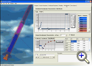
Deformations of a body result in appearance of local angles of attack and slip, influence on local aerodynamic forces and moments of forces. These forces are synchronized with changes of local angles. Local forces and moments lead to amplification or attenuation of flexible vibrations. At excessive development of flexible vibrations a structural failure can happen. Flexible oscillations result in Sloshing in Tanks and appearance of additional oscillation forces. Local wind effects depend substantially on flight velocity and altitude, the form of vehicle, its attitude and body flexible deformations. Even at constant velocity of flow near the vehicle surface vortexes are generated. It results in the composite and time-varying distribution of local loads on the surface. At high speed of flight the local spikes of pressure appear in separate parts of vehicle. For their modeling it is important to define zones of large local loads applying and their time history. Usually these zones are located close to transitions from conical to cylindrical surface forms or to place of joints of surfaces with more complex form. It would be better to avoid such connections, but it is impossible to remove them completely. The models for description of the typical local loads from vortexes are designed. The initial data for calculation of the distributed aerodynamic coefficients for the local forces are theoretical curves for particular vehicle or data from an experiment. The distributed forces produce the local loads participating in formation of elastic oscillations. Total (integral) loads cause forces and moments of forces determining the motion of vehicle center of gravity and are used in the unit Rigid Model of Vehicle Dynamics.
 view movie
5. Sloshing in Tanks
 Deformations of a body result in appearance of local angles of attack and slip, influence on local aerodynamic forces and moments of forces. These forces are synchronized with changes of local angles. Local forces and moments lead to amplification or attenuation of flexible vibrations. At excessive development of flexible vibrations a structural failure can happen. Oscillations of fuel and oxidant in tanks result in origination of forces and moments of forces in relation to all three axes of vehicle. Eigenfrequencies and oscillation frequencies of liquid depend on the form of tanks and their location at vehicle, the level of tanks filling by a liquid. Development of oscillations of liquid in tanks, in particular the flexible component oscillations, depend on vehicle motion and in turn influence this motion. For this reason it is necessary to include model of liquid oscillations in a structure of the generalized model of vehicle motion.
6. Different Engines Models
 Different models of liquid-propellant engines and solid boosters are used in the program. If turning engines are used for control of vehicle motion, it is necessary to consider two components of force and moment of force: static and dynamic. The first one is defined by the angles of engine turn in the relation to the vehicle body. The dynamic components of control force and the moment of forces are defined by angular acceleration of the engine and linear acceleration of its center of mass.
The electro-hydraulic steering actuators are considered for turning engines. At the stage of initial research the simple description of steering actuators as dynamical units of first and second order are used. For precise simulation it is necessary to use complex nonlinear model of actuators. Considering vehicle flexibility it is necessary to pay attention to the opportunity of aero-hydro flexible oscillations appearance.
For liquid-propellant engines it is necessary to add model of decrease the level of liquid in tanks and Sloshing in Tanks. For solid boosters it is necessary to use another model for center gravity drift during the vehicle motion.
7. Control System Analysis, Synthesis and Optimization
The program allows comprehensive analysis of dynamic properties of the closed-loop control system and its separate components including the flexible vehicle as control plant. In particular, for this purpose an automatic linearization of models is provided for any (arbitrary) moment of flight. These models may be represented in the form of state space or in frequency domain in transfer functions form. Program allows analyzing time responses and frequency characteristics, reducing dimensions of these models. Different methods of synthesis and optimization of regulators in time and frequency domains, including Kalman filtering approach, are used in the program. The prospective method of problem solution for flexible object consists of several sensors arrangement in different points of object and designing the integrated measuring and control system is executed. Accuracy of flexible vibrations parameters estimation and, therefore, control efficiency depends on choosing the sensor’s location points.
8. Order Reduction and Robustness Providing
Dimension of total model is a sum of models dimensions of vehicle, measurers, actuators, regulators, shaping filters which are used for stochastic processes simulation. General dimension depends on the chosen structure of control system and complexity of mathematical description of vehicle elastic properties. Usually this dimension is more then 50. Different procedures of dimension reduction for acceleration calculations at simulation and simplification of optimum regulator synthesis are used. The admissibility of any reduction can be checked by responses analysis. Because of considerable change of vehicle motion parameters, mass and elastic characteristics of the designed regulators must have robust properties.
9. Software Package Structure
At the first stage of work with the program it is necessary to input the constructive parameters of vehicle, data on mass variance and moments of inertia in flight, location and filling of tanks with fuel and oxidant, aerodynamic parameters, flexible parameters, initial position of vehicle, etc. Program interface allows changing numerous parameters at the screen (by mouse) and changing digital data directly in databases, represented in interface by tables. In the last case all changes are imaging on the vehicle picture. For accessibility the program is provided with the test example, which allows varying all parameters and saving them at the hard disk. Using the initial data the program automatically assembles nonlinear spatial model of vehicle. As the stability and controllability characteristics at various velocities and altitudes of flight are different, it is necessary to define the flight path and velocity profile beforehand. The state space vector is saved in the database for all flight time, as the base trajectory for further linearization of the complex model. The program allows managing the control system complexity and analyzing the influence of each factor on the control system dynamic characteristics.
The program enables:
- to find a linear mathematical model of any fragment of control system for any instant of flight in state space and as transfer functions for the given input and output vectors, and also for open loop system;
- to simplify a mathematical model and to check acceptability of simplification by comparison responses in time or frequency domains;
- to synthesize control system in frequency domain for any instant of flight and to check the results by frequency and time responses, and also by roots disposition;
- to synthesize control system in time domain, including Kalman filter and optimal regulator, to reduce the regulator and also to analyze the quality of control;
- to estimate the quality of control system with varying in time parameters by digital simulation, taking into account the external disturbances and measurement errors;
- to make schedules for any components of state vector during or after simulation, to display animations of a bending modes of an elastic axis for the flexible vehicle;
- to display the 3-D animation of vehicle in flight with capability to show bending and liquid oscillations in tanks.
The program consists of a set of separate modules. Adding and changing them allows to perform simulation for the broad class of flexible objects. As an example the animation of the deflection, first and second derivatives of centerline displacement are shown in the figures. The horizontal axis corresponds to the vehicle’s centerline. The vertical axis has the normalized scale. Circles mark points of vehicle conditional division into the discrete fragments with concentrated masses.
10. Development Prospects
Extension of program ability and scope for investigations of flexible aerospace constructions of different categories, for examples, returnable space vehicles, ekranoplanes (WIG-machines) and another perspective aerospace systems. Increasing quantity of units in the program library. Development of theory and program units for analysis and synthesis of more perfect control systems for flexible constructions.
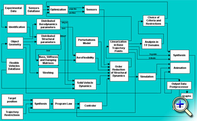 Project structure of comprehensive software (view large)
Effective software package for flexible aerospace vehicles comprehensive simulation and control design is offered. The discrete model of vehicle body is adequate to a beam with varying cross sectional properties.
Mass, stiffness and damping matrices calculated by a suggested technique correspond to a body with given distribution of linear parameters and acceptable step of digitization. The problem of model reduction by dominant harmonics is solved.
Local loads along the vehicle hull are calculated with respect to distributed aerodynamic forces, which depend on a local angle of attack, local airspeed and linear aerodynamic coefficients. Stochastic wind distortions are also taken into account.
Sloshing is represented by pendulums placed at the varying levels of liquids surface of tanks. Control actions effect and inertial load from engines turn are applied into gimbals hinge point.
Measurement modeling is based on models of sensors and noises. Bending vibrations in the points of sensors location are taken into account.
Control system design considers the given models of actuators. Control structure includes regulator and estimator, which can be reduced to filter. Optimum methods for the reduced model of control plant are used at synthesis of regulator. The plant dynamic model is obtained by linearization in the chosen points of nominal trajectory.
The closed loop system is exposed to various procedures of analysis in time and frequency domains. Correction of restrictions and criteria for synthesis task is carried out. The problems of identification of bending vibrations and distributed parameters of object are solved.
The software package includes the library of program modules designed on the base of mathematical models of flexible vehicle units and control system, taking into account such significant physical effects as structural flexibility, liquid oscillations, time lag of engines, local aerodynamic effects, etc. The adequate choice of the necessary program modules allows investigating the dynamic properties of any existing and prospective vehicle.
Demonstration of new program package for flexible vehicle simulation with user manual http://iiaat.guap.ru/iiaat/main/res_dev_projs/fvss_demo_eng.zip.
Project 2: Aerospace plane docking with Ekranoplane for water landing
 The cost reduction of useful mass injection on near-Earth orbit, expansion of functionality of space transport systems and ecology safety are among the major problems of space engineering. The fully reusable single-stage-to-orbit aerospace plane (ASP) with horizontal launch and landing might be ideally applied to meet such requirements. However, other demands and limitations, which bound with the state of the art of necessary technologies, force to consider a single-stage of ASP only as a target, which can be achieved stepwise. On the near-term steps of ASP improving it is necessary to consider them as a part of integrated transport system.
 ASP launch by use of heavy airplane is well known idea with definite advantages and drawbacks. The basic lacks are limitations on the available ASP take-off mass, on accessible parallax, the impossibility to place onboard plane the bulky cryogenic equipment and tanks for ASP filling by fuel components directly before its start, necessity of the specially prepared runway.
The concept of ekranoplane use for ASP horizontal take off and landing was proposed by A.Nebylov , Y.Ohkami and N.Tomita in 1995. It is shown that ekranoplane with own mass of 1600 ton is capable to carry ASP with initial mass of 500 ton and landing mass of 60 ton (Fig.1). It can solve the problems of ASP transportation from the base to the launch point which is far from human settlements and advantageous for forming the required orbit parameters, ASP fuel filling directly before launch. Ekranoplane provides ASP with the initial speed of Mach 0.6-0.65 in required direction that allows lowering the requirements to wing area and engines. Launch may be accomplished in any point of sea. Small ASP with 350 kg payload could be launched from ekranoplane in 400 ton mass.
Great advantages of “ASP-Ekranoplane” transport system are connected with ekranoplane use at ASP landing. Ekranoplane, apparently, is the unique transport mean for realization the progressive idea of docking to descending ASP the stage allowing to expand opportunities of its landing (Fig.2). ASP can be supplied with simplified landing gear when landing on moving ekranoplane. Large saving of mass will be provided if all equipment for such docking will be an accessory of ekranoplane. It permits to increase the payload of ASP up to 30% and to decrease the specific cost of launch. But it can be realized only on the base of serious fundamental study of three key elements considered together: ASP with horizontal start and landing, heavy ekranoplane and the complex of absolute and relative motion control with new requirements on accuracy and reliability.
Look also the paper “To space from Ekranoplane”.
Project 3: Flight parameters monitoring system for WIG-craft

The system was designed for a small (of length 14m) experimental WIG-craft (ekranoplane). It is intended for control and record of flight parameters:
- altitude of flight up to 5 m with accuracy 5 cm;
- speed up to 180 m/s with accuracy 0.1-0.2 m/s;
- roll and pitch angles with accuracy 0.1-0.2 deg;
- vertical overloads up to 3g with accuracy 0.06g;
- considerable sea waves height up to 1.5 m with accuracy 10 cm.
Primary sensors were: 3 special radioaltimeters, vertical reference system, multi-antennas DGPS receiver, etc. They were integrated with the aim of improving the accuracy and providing the fault-tolerance properties.

The precise radioaltimeters were specially designed in IIAAT:
- altitude (or distance) measured - 0-10m (at necessity - up to 100m);
- measurement error - not more than 5 cm under sea-way of number 0-5;
- measured parameter frequency range - 0-50 Hz;
- the operating RF - from X-range ( 9000 MHz);
- radiated power - 20 mW;
- power consumption - 2 W;
- output signal - digital and analog;
- mass - 1.2 kg.
The exterior of the radioaltimeter is shown in figures.
Field of Application: motion control automation systems for WIG-craft, hovercraft, air-cavity craft, hydrofoils, hydroplanes, special helicopters for installation and search-and-rescue works on sea; control complexes for production vessels and sea platforms.
Positive Effect of Application: improvement of controlled vehicle functional characteristics; reduction of fuel consumption and increase of motion safety.
Project 4: 3D-model construction of a surface represented by its photos
In many scientific and technical applications there is a necessity to construct 3D-model of physical object by the results of its observations. In particular, such problems arise in cartography, where it is necessary to construct a relief map of the area by the photos of the terrestrial surface. The similar problems exist in space navigation, robotics, endoscopy, etc.
The project is devoted to theoretical investigation and methods development of automatic determination of distance up to physical object and its separate plots with use of several optical images of the object. The digital cameras are used for input data obtaining. The photographic images of physical object and its fragments being obtained by different cameras simultaneously from different points or by one camera at the different moments differ from each other. The analysis of appropriate digital photos allows to determine visible fragments scale modification and to calculate a distance up to them. As a result the 3D-model of object can be constructed.
Project 5. Compressor of true-color images with controlled quality: very high compression
The AZ Compressor has been developed for a fast transfer of images through narrow-band communication channels. The work has been carried out over last four years at IIAAT of SUAI and meets the highest standards on the world market of applied software in this area.
AZ Compressor has a high speed of compression, similar to the speed of JPEG compressors. This feature allows for compression and image transmission in the real time mode.
A DOS version of the compressor has been also created. It can be used in monitoring devices regardless of their operating systems.
1) AZ Compressor allows user to compress JPEG, BMP or uncompressed TIFF true-colored images with high compression ratios.
2) The compressor meets requirements of mainly those users who need to have images compressed to very small file sizes without a significant quality loss. This feature is important, for example, for a low speed image transmission or when the memory capacity for image storage is very limited.
3) The AZ Compressor’s interface is simple and easy to use. Compression parameters are selected in such a way that the quality to file size ratio is determined automatically.
4) The AZ Compressor allows a compression of several images at a time.
5) Restored files have the TIFF True Color format.
Download Demo Version
Project 6. Astronaut Navigation System for Mars Planet Exploration
Astronaut Navigation System for Mars Planet Exploration - 06.pdf (508 Kb)
Project 7. Integrated Navigation System for blind peoples navigation in the city
Integrated Navigation System for blind peoples navigation in the city - 07.pdf (133 Kb)
Project 8. Fire Fighters Indoor / Outdoor Localization and Navigation System
Fire Fighters Indoor / Outdoor Localization and Navigation System - 08.pdf (513 Kb)
Project 9. The European project “E-SIT”
The project “E-SIT” (European Center for Space Informatics and Telecontrol) solves the problem of robots remote control through the information transmission network, built on the basis of the formation of several (at least two) controlled small satellites at low orbits, design, production and launch of which may be relatively cheap. The project is based on the international relations, installed many years ago in two technical committees of the International Federation of Automatic Control (IFAC) – TC 7.3 “Aerospace” and – TC 3.3 – “Telematics: Control via Communication Networks”.
The foundation of the project is built on the long period of cooperation between IIAAT SUAI (St. Petersburg, Russia, Director Prof. Dr. Alexander V. Nebylov) and Informatics VII: Robotics and Telematics ( University Wuerzburg, Germany, Chair Prof. Dr. Klaus Schilling)
Dr. A. Nebylov and Dr. K. Shilling have to be considered as coordinators of the project “E-SIT” from the Russian and the German side. Participation in the project of other countries representatives that have competence in the field of robots telecontrol and/or control of formation of small satellites, in the construction elements of the respective systems, is possible.
From the Russian side the project is supported by the Ministry of Education and Science of the Russian Federation in the frame of state task «Development of relative navigation and motion control systems for formation of small satellites for solving the meaningful tasks of monitoring and communication» for 2017–2019.
It is supposed that each robot has its own navigation system that allows it to measure the current position with high accuracy. The command post (CP) is located at a great distance from the robot, but the coordinates of CP are known. CP has to send control commands to robot and get from robot the information and other data used for commands development. The challenge is to build a communication channel “CP-robot”. The problem can be extended to the case of two or more (even n) robots control.
Using the Internet to transmit data is excluded for several reasons, one of which - a significant time delay in the transmission of signals through communication satellites in geostationary orbit, because it takes about one third of a second at the height of the satellite's orbit in 36 thousand km for transmission of forward and reverse signal, which will worsen the quality of robot control system.
Therefore it is required to construct a space communications system “CP-Robot” based on the low-orbiting satellites with an orbital altitude of about 600 km. Then, the signal delay is reduced by two orders of magnitude as compared with a stationary satellite, i.e. almost to zero. The reliability of space communications system without Internet use will be improved also, especially if the structural redundancy in low-orbiting satellites is available.
Each of n small satellites has one antenna, directed at the location point of the robot or the command post. The relative motion control system ensures their small removal from each other, not exceeding a given value D (about 10–30m). Such formation allows satellites continuously exchange information by non-directional radio links with low power consumption. In order to ensure the continuous control of robots it is required to have eight formations of n small satellites each, uniformly distributed on the orbit.
Project 10. Development of Amphibious Aeroboat of New Generation with Hybrid Engine
The project aims to create the next-generation amphibious vehicle that can help in solving the important problem of transporting passengers and cargo to difficult-reaching places. In Russia rivers and canals are covered with ice for almost more than half of the year, which makes it impossible to open navigation for conventional boats. There is an opportunity to use hovercraft, but they are very expensive to operate and have limitations in speed and maneuverability. The high-speed amphibious Aeroboat developed by us can be used round the year, even on completely frozen water bodies. Due to the amphibious property, Aeroboat operation does not require any naval or related infrastructure. Unlike boats having static air-cushion, Aeroboat uses a dynamic air cushion, which gives them numerous advantages. In the development of these vehicles, the main priorities will be ecological friendliness and energy efficiency. Therefore, hybrid engines will be used that significantly reduce carbon emissions. Nanotechnology is also planned for nanoscale particle layer formation in engines in order to reduce friction and increase of durability. Research, design and implementation of the optimal design of innovative Aeroboats is the main theme of this project.
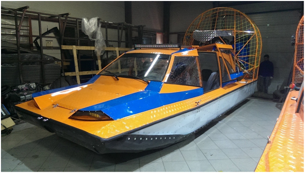
The movie of the designed Airboat is shown in the attachment
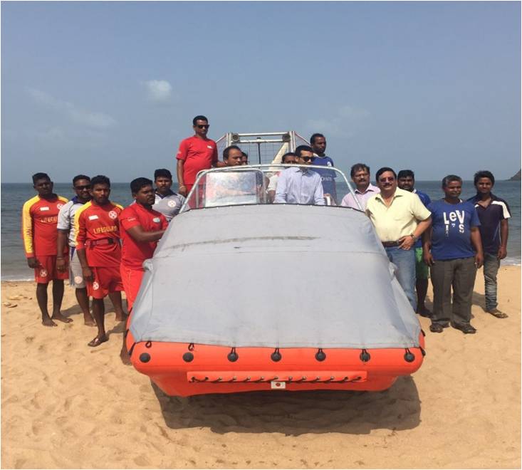
IIAAT-developed aeroboat for the Indian Ministry of Emergencies
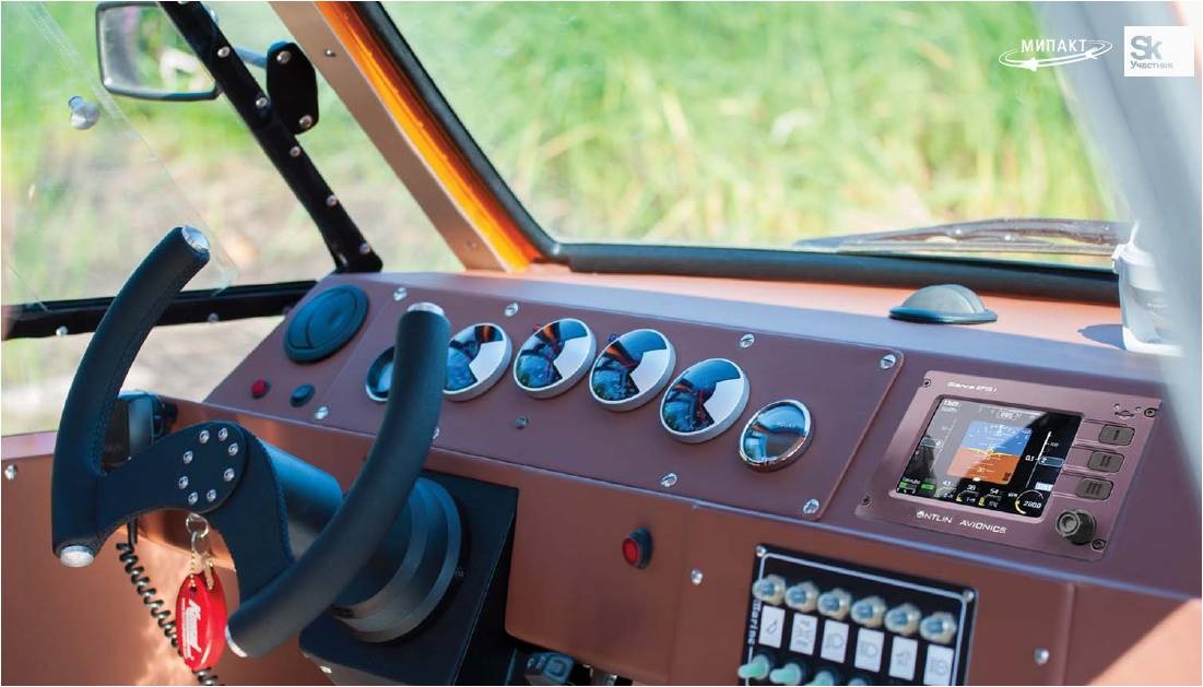
The "Glass Cabin" designed by IIAAT for aeroboats
Main scientific tasks of the project:
- Ensuring maximum speed of the Aeroboat at a given engine power.
- Maximizing fuel efficiency of the Aeroboat when driving along a given route.
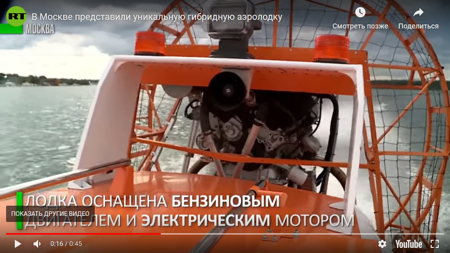
- Optimal relationship between the roles of the internal combustion engine (ICE) and the electric motor in providing the required driving mode. Synthesis of the optimal switch of energy flows on board.
- Scientifically grounded comparison of transport efficiency of Aeroboats and other high-speed non-displacement vehicles. Research of the most profitable transportation tasks for the Aeroboats and the rationale for the efficiency of purchasing innovative Aeroboats for services of Ministry of Emergency Situations, border guards, fishery protection, etc. Ensuring the success of participation in tenders for the supply of Aeroboats to the state structures of India, Sweden, Finland and other countries.
- Research to ensure the increasing role of solar batteries in providing energy efficiency onboard Aeroboats. The use of various fuel cells and energy storage devices with respect to the design of innovative Aeroboats.
- Research of methods and technical means to ensure the correct correlation of the positions of the center of gravity and the center of pressure of the Aeroboat both in the mode of navigation and in the mode of skimming.
- Research to ensure all-weather, all-season and amphibian Aeroboats, features of development of arctic zones, Siberian rivers and other hard-to-reach regions of Russia with poorly developed road network.
- Investigation of methods for monitoring the correct distribution of payloads (passengers and cargo) on Aeroboat in order to facilitate balancing and provide better conditions for entering the gliding mode.
- Optimization of the solution of the typical task of skimming for each type of Aeroboat and the features of its movement to ensure energy efficiency, stability and controllability of the apparatus.
- The rationale for the necessity and efficiency of implementing automation management tools in Aeroboats based on the use of all the latest achievements of automatic control theory and practice. Development of an unmanned Aeroboat version in the interests of the Ministry of Emergency Situations, the Ministry of Defense, emergency medical assistance.
- Theoretical and experimental study of the efficiency of nano-particles use in engines for reducing friction with reference to the energy-efficiency of Aeroboats.
- Use of satellite navigation systems and special low-Earth orbit satellites for unmanned Aeroboat control.